Building a Pole Barn Part 5

Welcome the last and final part about how I built a 12m x 5m barn for storing logs and implements on our small holding. It could also be used for sheep housing in winter. The project became more of a timber framed building than a pole barn; but you could easily adapt it and just put telegraph pole uprights straight into the ground (or concrete them in) if the land was suitable. The previous parts are here.
Part 1
Part 2
Part 3
Part 4

I must reiterate my disclaimer; I am not a structural engineer or a builder so the whole project is more ‘belt and braces’ than calculations and you should not rely on my design or construction for your own building!

After finishing the frame in Part 4 I then spread some of the shale around that we had dug up when building the house extension to provide a firm floor. I would have liked concrete but it was just too expensive for this project.

transport_box
Spreading the shale with my hydraulic transport box on my Alpine Tractor

The next thing I did was build a single brick pier around the base of each column. This is to ensure that the columns cannot move laterally in any direction even if hit with a tractor and to provide a support to keep the bottom rail for the cladding off the ground. It also means that I can pour preservative or perhaps waste oil down between the brick and the wood every year or two to stop the base rotting! The columns are also on a piece of damp proof membrane for this reason as well. The photo below shows this.

Bricks around foot of Column
Bricks around foot of  each column to help stop lateral movement of column and support the cross rails for attaching vertical boarding.

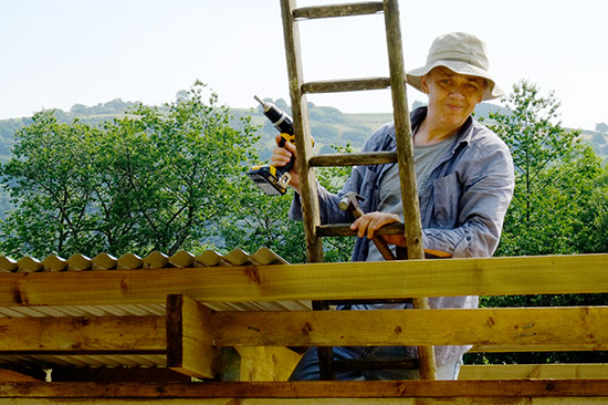
Horizontal rails were fixed across between the columns and the vertical boarding nailed to these with approximately 20mm air gaps. The photo below shows the cross rails and the boarding nailed on the back. All the timber was supplied treated so no need for any preservative other than on the cut ends and joints.

rails
Note the cross rails to nail the boards to. The bottom one supported on a brick and the centre one by a vertical timber off the bottom rail.

All that was left to do was cut all the side boards to the correct height and fix them before fixing the end cover strip which is fixed over (and through the roofing sheets) and covers the top of the side timbers to give a nice clean finish.

Barn
The finished barn with one closed bay and two open bays.

We’ve always been keen that it would be hidden in the landscape as much as possible so deliberately set in the lowest spot and formed a soil bank in front of it. This will be planted to screen it from view..

Barn Landscaped
The barn is landscaped into the surroundings so that once we have planted the soil bank in front of it it will be almost completely hidden.

So there you have it our barn that we built entirely ourselves. Some people have asked about costings and this is of course a lot more than if we had used telegraph poles and second hand roofing sheets. But I estimate.

Clearing the site/digging footings      £100
Timber Frame                                    £700
Roofing Sheets                                  £700
Timer Boarding and support rails      £500
Nails/Screws/Sand/Cement etc        £150
Total                                                   £2150

That’s it; I may put some light field gates on the openings to keep the sheep out (or in if I put them inside) and I may build a sheep handling area next to it.

So that could be another project!

Share

Building a Pole Barn Part 4

The fine spell of hot weather in July 2013 has meant that we can ‘crack on’ with getting the barn erected. Previous posts are here

Part 1
Part 2
Part 3

At the end of part 3 John and Jonathan were leaning smugly against the frame having assembled it. After Jonathan went back home to Spain, I (John) carried on fixing the 75mm x 50mm purlins across the rafters. These are necessary to support and fix the roofing sheets. I decided to use simple corrugated steel sheets for the roof. These are not too expensive or too heavy and are easily fixed. As the shed is partly open condensation should not be too much of a problem in winter. The sheets can be bought as plain galvanised or painted or plastic coated with the price and durability increasing accordingly. I went for the latter (most expensive and most durable) in a slate grey colour.

John and Purlin
Here you can see the purlins that John is resting the ladder on. They are nailed to the rafters and also have galvanised straps at places for ‘a belt and braces’ approach to gusting wind!

Each sheet of corrugated steel is 1m wide when lapped with its neighbour and they can be bought in any length to cover the exact span (remembering to leave enough overhang for the gutter). In my case I am overlapping them a tad more to save cutting the last sheet. It is of course essential that the first sheet is positioned correctly or they will all start ‘running out’ of alignment.

shed2
John marks where to fix the sheets by hooking a line over the last fixing and along the centre of the purlin.

The position of the fixings can then be marked. The Tek screw fixing are self cutting but I found it easier to either drill a pilot hole or just bang a small nail through.

John marks where to fix the sheets
The sheets are fixed through the top of the corrugation, not the valley, to prevent leaks. The screws are self tapping but I found it easier to make a starter hole with a nail.

If you don’t carefully mark the line of the purlin you risk having a hole in your roof and nothing underneath to screw into!

The Tek screw has a rubber collar
The Tek screw has a rubber collar to prevent water ingress.

The screws should be tightened down until they are holding firmly but not crushing the corrugation. They can be capped of with plastic caps (a dab of silicone under the cap before putting them on is not a bad idea to stop them coming loose).

It is screwed into the purlin with an 8mm nut driver on an electric drill
Here you can see the fixed roof with another sheet waiting to be fixed.
Here you can see the fixed roof with another sheet waiting to be fixed as I work my way across the roof.

So the roof will soon be finished and then I only have to fix the side cladding boards and do a bit of tidying up etc which I hope to show in the last part.

Go to Part 5 (the finished barn!)

Share

Building a Pole Barn Part 3

If you missed Parts 1 and 2 you can find them here
Part 1
Part 2

The foundations  were finished around July 2012. Each pier has a galvanised anchor strap set in it an the columns will be secured to these.The foundations are finished

The foundations were finished in around July 2012

Unfortunately everything then went on hold due to a combination of the wet weather and us starting the building work on the house. I found a local sawmill here in Carmarthenshire and Rocco at Talley sawmills sourced some larch and cut it to my specifications. Rocco is definitely a ‘character’ and not necessarily the fastest but he found, cut and treated all the timber for me for a very reasonable price. So I’d definitely suggest that you ‘sound out’ your local saw mill for a project like this.

In essence I am using 200mm x 200mm upright columns each with a cut in one end to accept 200mm x 100mm cross beams; these will be bolted together. Then rafters will span across the barn and these are  200mm x 100mm above each column with (2) 200mm x 50mm rafters in each bay.The latter will be secured by upside down joist hangers. Each column will rest on the concrete pads with a d.p.m. and be secured to the galvanised straps in the concrete base.

Sounds complicated but should become obvious from the photos.

It was several weeks before the timber was delivered and things gradually ‘slipped’ so it was not until June 2013 when Jonathan, our son, came home again and he was press ganged into helping with some of the heavy lifting that we started the build. When we first erected the columns we decided that the barn was just going to be too tall. It would be fine on a working farm; but would be too visible in the landscape. So with the help of a chainsaw I reduced the columns to a height that gave sufficient access for a tractor but that was not too high so as to be visible from the house and from the other side of the valley.

_DSF1155
After Erecting the 200mm x 200mm Columns the 200mm x 100mm cross beams are drilled and bolted in place.
_DSF1202
Then the Rafters are Placed Across the Span

Getting the first cross pieces into place was a tad tricky as nothing was really secured and it was all a bit wobbly! But after we started to drill and bolt the joints the frame started to become more rigid. We then had to constantly check that columns were plumb and that distances were the same between openings etc. But after around two days work we had the basic frame in place. It still needs horizontal rails to board the external boarding to and needs some purlins/battens across the rafters to fix the roofing sheets to.

_DSF1182
The 200mm x 50mm Rafters are Put in Place First and Secured with Joist Hangers
_DSF1223
The barn frame takes shape; just the 4 thicker (100mm) and heavier rafters to be put in place; one above each column. Luckily a friend dropped by at just the right moment to help with the lifting!

We also found that it needed some triangular braces between horizontal beams and columns to increase its stability.So these were duly added and treated with preservative.

_DSF1234
Cross bracing and detail showing bolts and joist hangers
_DSF1233
The Finished frame for the barn; now you can see why we didn’t want it to stand out in the landscape. The excess soil heaps will be landscaped and planted to form a screen. It is really important to us that it is not visually intrusive.
_DSF1230
John and Jonathan prove that it will not fall down by leaning on the finished frame!

But at least it is starting to look like a shed. The next post will show the roof and boarding, just as soon as I’ve sourced these! Whilst I don’t have prices for these yet I’m expecting the whole barn to cost around £1500 – £2000 which I don’t think is too bad for a 12m x 5m barn. It could be built for half of this by careful sourcing of things like second hand roofing sheets etc.

Disclaimer; I am not a structural engineer or a builder so the whole project is more ‘belt and braces’ than calculations and you should not rely on my design for your own building!

Go to part 4

Share

Not So Grand Designs Part 5

The story of our property refurbishment and building 2 extensions has been documented in a very haphazard manner in various posts.

Part 1 Here
Part 2 Here
Part 3 Here
Part 4 Here

sun_room_rear
Sun Room from the Rear  Showing the Accoya cladding

The photo above shows the new sun-room from the back; the wood cladding is Accoya, a preserved timber, that is meant to last for 60 years and is very stable in wet weather. The gutters will be replaced with something more sympathetic when we get round to painting the rest of the house! You can just see the new solar hot water panels on the far roof of the house. The windows were supplied by the Danish company Rationel Windows.

sun_room_front
The Sun Room from the Front showing the Solarlux Bifold Doors

In view of the extreme weather in Wales we sourced the aluminium bifold doors from Solarlux in Germany.

porch
The New Entrance Porch with the new utility room behind

The new entrance into the new porch provides a storage area for coats and shoes etc. To the rear is the new utility room housing the boiler for the underfloor heating etc. There is an external log store.

kitchen
The New Kitchen fitted by Wade Furniture

Barry Wade of Wade Furniture, a local cabinet maker, made and fitted the new kitchen for us.

living_room
The Living area with Mezzanine above

The living area had to have sufficient space for our Quad ELS63 loudspeakers made by Quad hifi in 1963! The office area above is accessed by the new spiral stairs.

stairs
Spiral Stairs with UFH Manifold

The Spiral Stairs were made by Woodside Joinery, Cwmbran. Their workmanship was first class. The underfloor heating manifold has yet to be ‘boxed in’ i.e. when John gets round to it!

sun_internal2
The view out of the Sun Room

The sun room with its views down the valley has proved to be John’s favourite room. It is a lovely light, airy room.

sun_internal
The Sunroom with bookcases and one of John’s Photos

The sunroom also provides plenty of storage for our books.

bathroom
The ensuite bathroom

The new ensuite shower room has John’s niches in the wall for shampoo etc as he hates those wire basket things!

So there you have it 7 months of building work, a lot of expense but we have a lovely warm environmentally friendly house that we love. Now John just needs to get on with the outside!


Share

No So Grand Designs Part 4

Part 1 is here.

Part 2 is here.

Part 3 is here

Happy New Year. Well it’s 2013 and the blog has suffered because we’ve been hunkered down for the cold weather in our temporary accommodation. The building work was meant to be finished by the end of November but has been delayed by the anhydrite screed not drying out fast enough. It was meant to take 60 days but has still been measuring around 12% moisture in places. It needs to be around 0.5% for tiling. However, after spending the Christmas break grinding off the top surface of the screed with a grinder it has started to dry quite quickly and we are hoping that the builders can start tiling the floors on their return after the New Year break.

The photos below are now out of date but show some of the progress since the last posting.

Water Services
The water services are installed, sleeved in conduit and you can see the start of the bathroom stud wall.
UFH1
The Underfloor Heating Pipes Come together at the Manifold Position
UFH2
The Underfloor Heating Pipes are Laid in 10 Zones on Celotex Insulation; with Perimeter Insulation
screed
The Anhydrite Screed is Pumped in to Cover the UFH Pipes, note the ‘tripods’ that are Positioned Before with a Laser Level.
Bathroom Partition
Bathroom partition is in place with lots of sockets for the Hi-Fi and TV!
Shower Wall with recesses
Shower Wall ready for tiling with John’s patented bottle recesses
Sunroom Window
Sunroom Window in position
Kitchen
Kitchen leading through to the sunroom, awaiting plastering.

Part 5 is here

Share

No So Grand Designs Part 3

Part 1 is here.

Part 2 is here.

By the beginning of August 2012 the concrete has been poured into the footings, the below ground block work done, the slab poured and block work is starting to rise above ground.

The blockwork to the utility room and porch starts to go up
The block work to the utility room and porch starts to go up
The sun room also starts to rise from the ground.
The sun room also starts to rise from the ground; note the 80mm of insulation.
New drain runs for surface and foul water
New drain runs are installed for surface and foul water.

Meanwhile inside the original bathroom floor for some inexplicable reason was finished above the height of the bedroom floor. This means that the bathroom floor needs to be broken up to lay a new slab at the correct height. It turns out to be fortuitous as the subfloor is full of water from a leaking pipe.

Meanwhile inside we 'Kango' up the bathroom floor
Meanwhile inside we ‘Kango’ up the bathroom floor and deposit the concrete in what was our bedroom. Note the new steel joist.
Roof Construction
The Roof to the Sunroom Starts to Take Shape

Part 4 is Here

Share

Not So Grand Designs Part 2

Part 1 of our building project is here.

The builders Jones and Maher of Carmarthen have continued demolishing the interior of the house and by the first week in July they had inserted the new structural steelwork to support the new mezzanine level and where we are extending our bedroom into the existing bathroom (which is really too large).

The New Beam is Inserted to Support the Mezzanine
The new steel beam is inserted to support the Mezzanine

John tends to see Phil the site foreman most days and we’re pretty sure that he (Phil) now thinks that he has a client with OCD. We’ve spent the best part of a year planning this work to include the extensions, underfloor heating, increased insulation in the floors and vaulted roof, solar hot water, and a new kitchen (as we are relocating some of the old one into the utility room). So getting is a ‘right’ as possible is one of our main aims.

Much of our time is spent just trying to think ahead; for instance it is necessary to decide on the floor finishes as the finished floor heights for the extensions will need to be calculated taking these into account. As the windows and front doors are being ordered from Rationel, a Danish company (with manufacturing plant in Poland) and come pre finished it is necessary to decide on colours at the outset; so that they can be ordered in advance to arrive at the correct time.

Of course having decided to start work in summer the weather has remained extremely wet, which hasn’t helped with digging the foundations for the new extensions.

The foundations are dug for the new sunroom
The foundations are dug for the new sun room

The new concrete is then ‘tied’ to the existing footings by inserting and resin bonding steel bar into the original concrete foundations.

The excavations for the porch and utility room
The excavations for the porch and utility room show the steel tied into the existing foundations. The vertical steel bars denote the level of the finished concrete. As the house is sat on solid shale there is no need for excessively deep footings.

Go to Part 3

Share

No So Grand Designs Part 1

After moving here to Wales we had the idea of building a porch to help reduce the draught into the house in Winter. This was quickly followed by the idea of building a ‘sun room’ on the other side of the house. Oh how naive we were!!

Realising that this needed to be done well we set out to find someone to could put our ideas on paper. This lead us to  local architects Llewelyn Lewis Sennik (Gareth and Anita) who also concluded that if we were going that far we might as well have a Utility Room as well and also do any other upgrading at the same time.

We did consider installing a ground source heat pump but ultimately decided against this on the grounds of cost. As we already have solar PV providing some free electric and indexed linked payments of around £1500 per annum and our own woodland providing us with free wood for the woodburner we decided that a few hundred pounds of oil a year will be all that is needed to keep us warm in the coldest periods (I think that is what economists call a cost benefit analysis!) with all the extra insulation we are installing. I estimate that we should receive around £600 or £700 a year more in payments for the PV panels and solar HW than we will payout in energy costs.

Yes we are going to gut our home! This is how it looks now.

To cut a long story short, after a 6 month battle with the planners (including having to employ Planning Consultants) we ended up with Planning Permission to build two contemporary timber clad extensions. In addition we would ‘gut’ the house to add underfloor heating throughout, upgrade the already good insulation to ‘super standard’ and refit most of the house. In addition we would be improving the heating and fitting Solar Hot Water Panels to compliment our recently fitted solar PV Panels.

South Elevation
Proposed South Elevation Showing 'Sun Room' window

So after 18 months of design, trauma and an ever increasing budget we moved out of the house on the 11th June 2012 (into rented accommodation) and the builders moved in to start gutting what most people would see as a perfectly adequate dwelling. Mad or what?

The House Before We Started!

And after a week or so the builders stripped out the house now the long process of putting it back together starts! It now looks like the photo below.

The Gutted Interior
The Gutted Interior

Part 2 is here.

Share